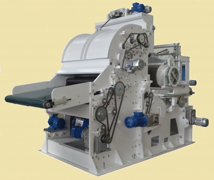
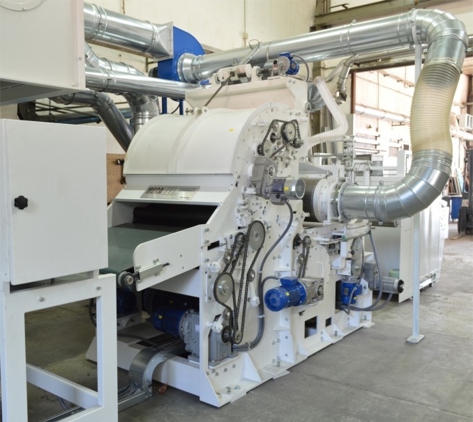
Airlay Card mod. CA300
Technical features:

Working width: from 1000 to 4000 mm
Overall width working: width +100mm
Range of fibres all new and reclaimed Fibres, including blends of natural as well as vegetable fibres. The dtex of fibres goes from /= 30 dtex, the fibre length goes from 0,8/10 mm to a maximum of 90 mm.
The capacity of the machine, regarding certain fibre fineness, depends of the single fibre itself.
Weight of nonwoven batt: 150 – 3000 (g/m2)
Production new fibres: w/width: 1000 mm: 250 kg/h
w/width:: 2500 mm: 600 kg/h
Reclaimed fibres: w/width:: 1000 mm: 500 kg/h
w/width:: 2500 mm: 1200 kg/h
delivery speed: 1 - 20mt/min. (others on request)
volume of circulating air: ~ 2 x max. 18.000 m³/h, 2 x max. 15 kw inverter controlled – depending on the machine’s working width
Compressed air: 7 bar
Installed power: ~ 60 kw – depending on the working width
Electrical load: 3 x 380 V + N + E / 50 Hz
Weight of machine: depending on its working width
Dimensions of machine:
Length: 3500 mm
Width: distance between sidewalls + 1000 mm
Max. Height: 3000 mm
Description:
1. HOPPER FEEDER:
It is composed of:
- a motorized spreader for the feeding of the fibres.
- a chute feed with photocells for the indication of min. and max. level
- two feeding rollers and one spiked roller, they are driven for the discharging of the material,
- one PVC feeding conveyor driven by a gear motor
- a vertical spiked lattice, controlled by a gear motor with frequency inverter for the speed adjustment
- a spiked stripper lattice on the feeding side, which is controlled by a gear motor with frequency inverter for speed regulation.
- a spiked lattice on the delivery side which is controlled by a gear motor.
- a volumetric feeding unit, placed on the exit side of the hopper feeder, including photocells for indication of min. and max. level of fibres, a vibrating wall and driven discharging rollers
1.1. the Weighing conveyor - for the feeding of the carding machine
It is composed of:
- a PVC belt collecting the material which exits from the volumetric dispenser.
- The belt is mounted on weigh cells,
- a gear motor with frequency inverter for the speed regulation.
- an electric control panel
2. THE FEEDING UNIT
The feeding unit consists of an apron (1), three feeding rollers (2) and one lickerin (3). The fibre which is to be carded, coming from the chute feed will be deposited on the feeding apron which will take them to the three feeding rollers which will pass them on to the lickerin.
The feeding apron is made of PVC and two rollers. It has lateral guides for an even movement.
The three feeding rollers are covered with steel clothing. The distance between the latter and the lickerin is adjustable according to the fibres which are to be carded.
The speed of the feeding apron and the feeding rollers are controlled by a gear motor with inverter.
The lickerin is covered with steel clothing and is driven by a motor with pulley. The speed of the lickerin is converter controlled.
3. THE CARDING UNIT
The carding unit consists on a main cylinder Ø 600 mm, which is covered by a special saw tooth clothing for a better forwarding of the fibres, and two workers and strippers, which also have a saw tooth clothing
The distance between each worker and stripper pair is adjustable. The same applies to their distance to the main cylinder.
The incoming fibres will be collected by the main cylinder, made parallel by the workers and forwarded to the batt-formation area.
Two gear motors drive the two workers as well as the strippers. Their speeds are independent and controlled by an inverter.
The main cylinder is driven by a motor with pulley and its speed is controlled by an inverter.
4. THE NONWOVEN BATT FORMATION
The nonwoven batt formation consists on a blowing device (across the working width), a perforated drum with an incorporated adjustable suction device, of a perforated delivery apron and a suction drum below the delivery apron. There are ventilators fitted to the upper and lower drum for air suction. An inverter adjusts the amount of suction.
The blowing device is driven by a motor with pulley and the its blowing strength is inverter controlled. The rotational speed of the (upper) perforated drum is inverter controlled in order to synchronise it with the perforated delivery apron, whereas its working position (encoder controlled) can be adjusted vertically as well as horizontally. This adjustment depends on the kind of fibres, its weight and the thickness of the nonwoven batt that is to be produced.
The bottom suction drum has an opening along its upper side. The size of this opening is adjustable; the delivery apron runs right on top of it.
The perforated delivery apron is guided by three rollers and driven by a gear motor. Its speed corresponds to the inverter controlled delivery speed of the airlay card.
The nonwoven batt formation area finds itself between the upper perforated drum and the area of the opening of the lower drum right below the perforated delivery apron. The fibres coming from the lower perforated drum and they are laid down on the perforated delivery apron.
The orientation of the fibres and the and the thickness of the nonwoven batt depend on the adjustment of the airflow as well as the rotating speed of the upper drum and the speed of the delivery apron.
The airflow coming from the blower (6) enables a uniform fibre distribution and an even surface of the batt at the delivery point of the airlay card.
5. ELECTRIC CABINET
Related media

